
Communication connectors and terminals
INSTALLATION AND WIRING
49
2
USB device communication
A USB (Ver. 1.1) cable connects the inverter with a personal computer.
Parameter setting and monitoring can be performed by FR Configurator 2.
NOTE
• For the details of FR Configurator2, refer to the Instruction Manual of FR Configurator2.
2.7.3 RS-485 terminal block
Communication operation
The RS-485 terminals enables communication operation from a personal computer, etc. When the PU connector is connected
with a personal, FA or other computer by a communication cable, a user program can run to monitor the inverter or read and
write parameters.
Communication can be performed with the Mitsubishi inverter protocol (computer link operation) and Modbus-RTU protocol.
(For details, refer to the FR-A800 Instruction Manual (Detailed).)
NOTE
• To avoid malfunction, keep the RS-485 terminal wires away from the control circuit board.
• For wiring of the RS-485 terminals used with a plug-in option, lead the wires on the left side of the plug-in option.
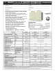
Interface
Conforms to USB1.1
Transmission speed
12 Mbps
Wiring length
Maximum 5 m
Connector
USB mini B connector (receptacle)
Power supply
Self-powered
Conforming standard
EIA-485 (RS-485)
Transmission format
Multidrop link
Communication speed
115200 bps maximum
Overall length
500 m
Connection cable
Twisted pair cable (4 pairs)
Terminating resistor switch
Initially-set to "OPEN".
Set only the terminating resistor switch of
the remotest inverter to the "100Ω" position.
OPEN
100Ω
+-+
TXD RXD
-
VCC GND
+-+
TXD RXD
-
VCC GND
RDA1
(RXD1+)
RDB1
(RXD1-)
RDA2
(RXD2+)
RDB2
(RXD2-)
SDA1
(TXD1+)
SDB1
(TXD1-)
SDA2
(TXD2+)
SDB2
(TXD2-)
P5S
(VCC)
SG
(GND)
P5S
(VCC)
SG
(GND)


 England
  Deutschland
  France
  Italia
  Polska
  United Kingdom
  Россия
  Nederland
  España
  Magyarország
  Sverige
  România
  Portugal
  Colombia
  Suomi
Suomi  New Zealand
  Česká republika
  Türkiye
  Danmark
  日本
日本